The plan
Scan head
My scan head will probably be quite similar to Dans. I plan to have two pieces of aluminum separated by three screws acting as coarse approach. One of the pieces will hold the sample while the other one holds the screws and the piezo scanner. The piezo scanner will be made by a simple piezo buzzer with one of it’s electrodes cut into 4 quadrants. This method was invented by John Alexander who also used it in a homemade STM.
Electronics
My plans for the electronics are quite different from Dan Berard’s. I have decided to opt for an analog feedback control rather than a digital one. That being said I have borrowed some designs such as his preamp.
This is a block diagram showing the different parts of the STM electronics.
The Arduino tells the 4ch DAC to produce a raster pattern with it’s X and Y outputs. This causes the piezo to change shape and the scanning tip to move across the sample surface. The resulting tunneling current signal is amplified by the preamp. The error amp and integration amp process this signal into the desired Z position which is then sent to the piezo control circuit. The arduino reads the Z signal and sends it to the computer which (if everything works) produces a nice image.
What is STM?
All this might sound very mysterious to you reading if you don’t know what STM even is. Well since I’m interested in this stuff, I am also happy to explain it.

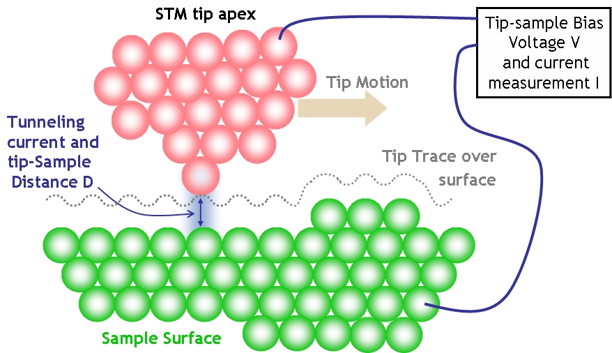
Image taken from Wikipedia
STM stands for scanning tunneling microscopy. It is a technology in which you bring a very sharp needle very close to a conductive sample. If the sample and the needle are given a small voltage potential, and they are close enough, a tunneling current will occur. This is because of a phenomenon known as “quantum tunneling” in which particles (electrons in our case) can go from one place to another, even though they have a zero probability to be anywhere in between. This tunneling current is very sensitive to distance, so when the tip is moved across the sample the tunneling current changes with sample height. If the tip is scanned across the sample an image of the sample topography can be produced. Given that the microscope is built well enough, it can image individual atoms! Often the height of the needle is adjusted so that the tunneling current stays the same. In this case the height of the needle is what is used to produce the image.
For The Future
I have received the parts I have ordered and I am ready to start building! Tomorrow at school I will start working on the scanning head. (I dont have a drill press at home). My first goal is to achieve a tunneling current. After that I will start trying to produce a constant height image, after which I will get into the feedback electronics. This method of doing one thing at a time will hopefully save me some trouble shooting. I will probably also post some pictures of my notebook. I have used it for most of the planning of this project. It probably gives a more detailed (although harder to read) picture of my planning.

No comments:
Post a Comment